Preventing Ship Allisions of Bridges
Tampa Bay 1980 Allision
Sunshine Skyway Bridge
The bridge in the photographs of faux pier islands (dolphins) shown earlier is the Tampa Bay bridge that was constructed in 1987 and is now in use. It replaced a bridge that had been damaged by a ship allision in 1980.
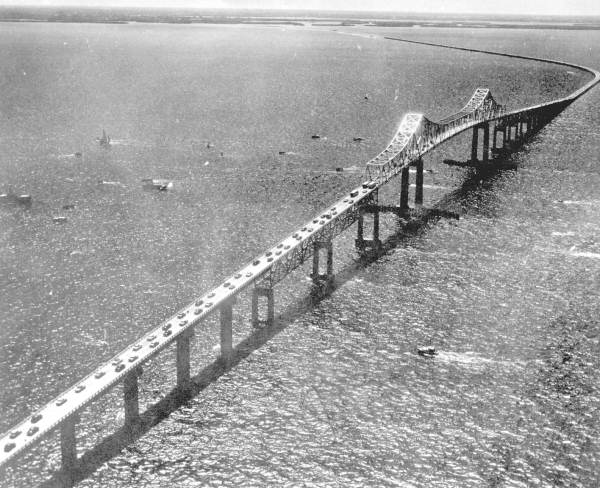
This is the longest bridge in Tampa Bay, Florida, crossing the shipping channel that leads to the ocean. It is the shipping gateway of Tampa Bay, referred to as the Sunshine Skyway Bridge.
The original bridge was opened in 1954, with two lanes of traffic (one lane in each direction). The main span, over the main shipping channel of the bay, was a truss bridge with overhead inverted arch that slopes downward from the ends of the span.
This arching created a cantilever at each end of the main span, holding up a suspended span between the arch ends.
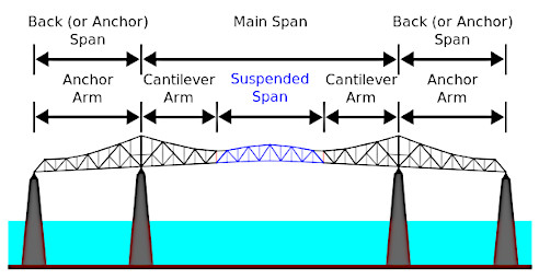
The suspended span between cantilevers allows the main span to be somewhat longer than the other spans of the bridge, but not as long as other types of bridges.
A second identical bridge was opened in 1971, constructed parallel to the original bridge, to add two more lanes. Having a second bridge in parallel provided two lanes of traffic in one direction on one bridge, and two lanes in the other direction on the other bridge.
1980 Allision
On the 9th of May 1980, a 165 meter long freighter, that had come in from the ocean, tried to cross under the Sunshine Skyway Bridge during early morning squalls (sudden heavy rains).
The ship missed the channel, and ended up under the next span over, alliding with the bridge pier at the far end of that span.
The freighter struck the west bridge, which was the original bridge that opened in 1954. Three spans fell: the two spans that were held up by the bridge pier that was allided; and the next span over which was the main span.
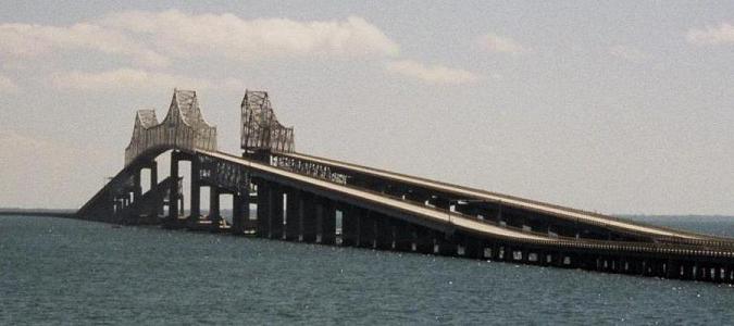
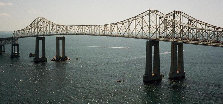
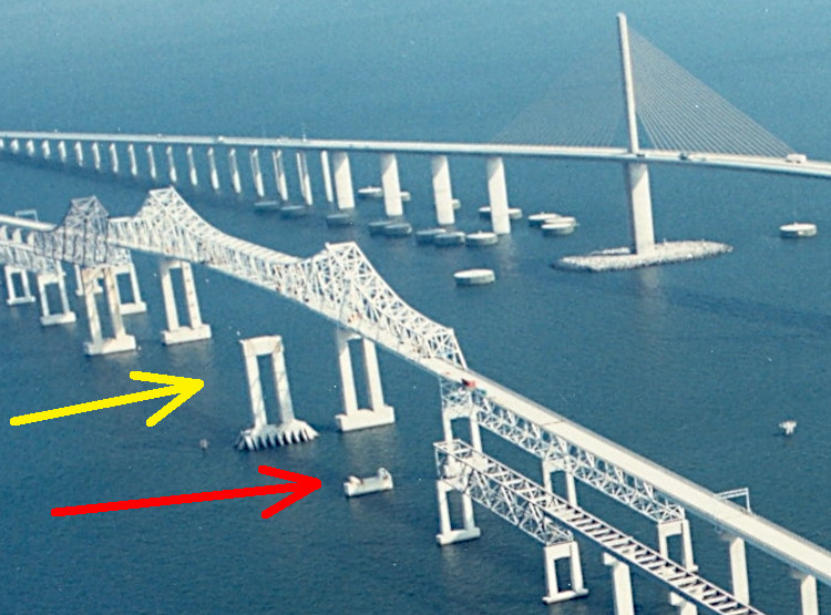
The yellow arrow shows the ship channel under the old bridge. The water was deep enough at the red arrow for that to be part of the channel, but the truss bridge could not span a channel that wide. The bridge piers had to be too close together because it was a truss bridge.
The new bridge span, over the ship channel, is a cable-stayed bridge instead of a truss bridge. Cable-stayed bridges can have longer spans than truss bridges, making the ship channel wider under the new bridge.
Note how the bridge pier between the arrows seemed to have fenders. That would not help with larger ships that have bigger bow overhangs which strike bridge piers high above the fenders.
The bridge pier that was rammed (at the end of the red arrow) broke low to the water, despite being hit high above the water, due to leveraging of the concrete piers by the bow overhang of the ship.
Leverage
The portion of the freighter that struck the bridge pier was the right (starboard) side of the ship near the bow (front of the ship).
Ocean going vessels, like this freighter, have flared sides on the bow to deflect waves in the open ocean. That causes the bow to protrude outward from the rest of the ship in the part of the ship that is near the front of the ship. That protrusion will be referred to as the bow overhang in this discussion.
The larger the ship, the further out the bow protrudes (the larger the bow overhang). As a result, larger ships will strike bridge piers higher up from the water surface.
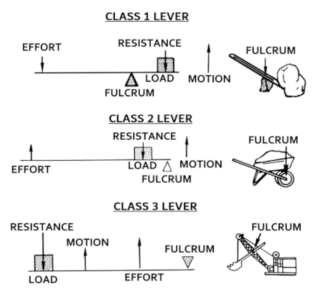
If the bridge piers are concrete, as in this case, since concrete is stronger in compression than in tension, besides breaking where it is struck, it could snap far away from where it is pushed (at the base/fulcrum of a lever).
In terms of lateral forces, think of a concrete column as being like a bread stick or pretzel stick.
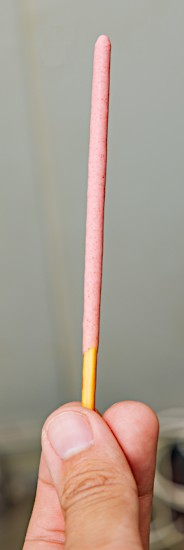
Say you firmly hold one end of the bread stick or pretzel stick, and push sideways (laterally) against the other end.
The bread stick or pretzel stick could break near where it is held firmly, because of leveraging, similar to the Class 2 Lever in the following diagram:
Pier leveraging by alliding ships that are taller with larger bow overhangs is a likelihood that is increasing in severity.
The National Transportation Safety Board issued the following recommendation, in their 1981 report of this 1980 ship allision of the Tampa Bay Bridge: