Preventing Ship Allisions of Bridges
Baltimore 2024 Allision
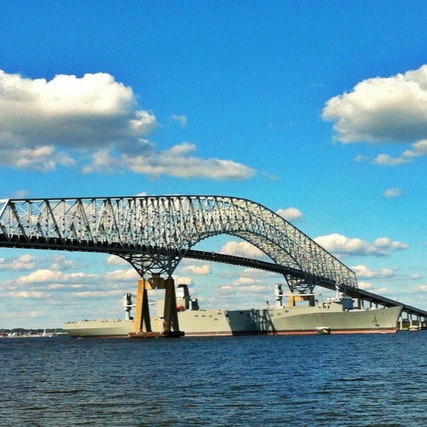
Francis Scott Key Bridge
On the 26th of March, 2024, the Outer Harbor Bridge in Baltimore, Maryland, officially called the Francis Scott Key Bridge, collapsed after being struck by a large container cargo ship. The ship was reported to be drifting without power after leaving the nearby inland Port of Baltimore.
The alliding ship was not escorted by tugboats, and the bridge had many design errors. Both factors caused the bridge collapse, resulting in renewed calls for the United States to improve its bridge designs and require use of tugboats in its inland waterways.
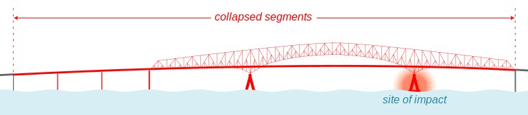
The ship struck a bridge pier on the side of the ship channel (waterway) that passed under the main bridge span, knocking down the two bridge spans that were supported by that bridge pier, which in turn knocked down additional spans on the other side of the main span due to the seesaw effect and lack of arm-to-pier bracing.
The length of the alliding cargo ship was 299 meters, while the bridge span was only 366 m, violating a basic rule of thumb of bridge design, which states that a bridge span should be at least 2 or 3 times longer than the length of the longest ship that will pass under it.
Weak Piers
The two main bridge piers, holding up the main bridge span over the shipping channel, were pairs of inclined hollow rectangtes tilting into each other, forming hollow triangle ends.
Each pier column was tilted into another tilted column, for the columns to hold each other up, instead of only holding up the bridge.
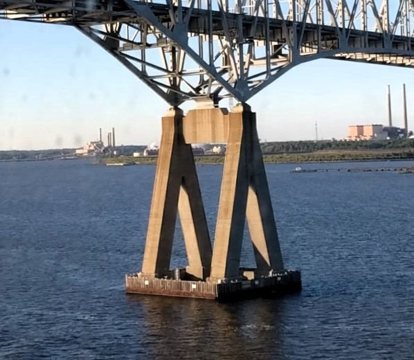
Concrete is stronger in compression than in tension, and designing a concrete column to lean into an oppositely leaning concrete column will cause both columns to fail if either one fails.
The columns should have been vertical, and spaced further apart. Boxes of steel trussing above separate vertical columns could have temporarily held the bridge up in the event of a limited number of columns being removed by allision (giving time to evacuate the bridge).
Seesaw Effect
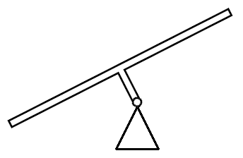
The hollow concrete triangle shape, of the main bridge piers, converges to a fulcrum, at the apex of the triangle, where the contact interface between the pier and the bridge is only a line (one dimensional), causing the bridge to seesaw, with the pier as a fulcrum, if the other pier fails. That is what happened (viewed from the other side of the bridge):
On the right in this view, notice the end of the truss bridge initially lifted up in the air, then came back down like a seesaw, destroying that girder span pier.
Collapse of the girder pier and span could have been avoided if the seesaw effect had been reduced.
Forth Railroad Bridge
The seesaw effect could have been reduced
by having a multidimensional contact interface
between the bridge and the shipping channel piers.
If that interface was planar instead of a line
One way to make the interface two-dimensional is having four or six columns instead of two columns on the side of the waterway. Earlier we mentioned an advantage of extra columns was to make the bridge take longer to fail (allowing more time to evacuate people to safety). Now we mention another advantage of extra columns: to reduce the seesaw effect.
The topic of extra columns for truss bridge piers was brought up during the late 1800s, in the design of the Firth of Forth Railroad Bridge.
The original design called for linear contact interface at the anchor-to-cantilever piers. However, that plan was rejected by independent engineers that vetted the design, causing the design to be changed as follows:
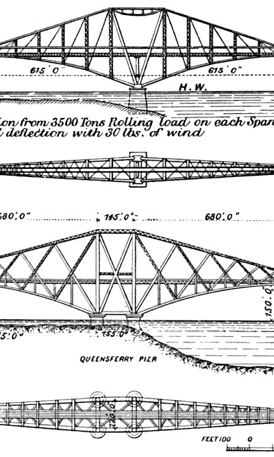
The reason for replacing the seesaw design with four columns in the Forth bridge design was to reduce deflection of the bridge deck when two trains approach from opposite directions.
That same spreading of load transfer would reduce the seesaw effect.
Moment of Inertia
Another design error, worsening the seesaw effect during failure, was to have the bridge deck (anchor and cantilever arms) vertically offset, up from the seesaw fulcrum.
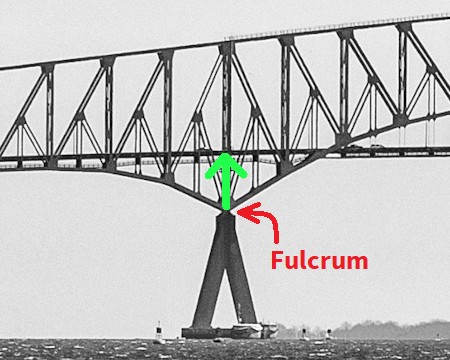
If a seesaw had to be used (as was done), the pier should have extended to the bridge deck, with fulcrum at the bridge deck (top of green arrow). The diagonal bracing below the deck would still be used, connecting to the pier below the fulcrum, not at the fulcrum.
Having the pier too short created a moment arm that worsened the collapse. We explain by considering classic seesaws.
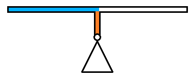
A seesaw is a straight beam with a seat at each end. The beam rests on a fulcrum below the middle of the beam. Children sit at each end balancing the beam.
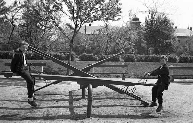
Each half of the seesaw beam is a moment arm (lever). To get more leverage, sit further out on the beam.
Half of the beam is always on one side of the fulcrum, regardless of whether the beam is horizontal or not. In the photograph above, the beams of unused seesaws in the background are not horizontal, but still have half of each beam on one side of the fulcrum (and the other half on the other side).
Pushing the beam up and down moves the beam up and down, as the beam rotates around the fulcrum.
Pushing the beam toward the fulcrum, instead of up and down, does not move the beam, because it is fixed at the fulcrum.
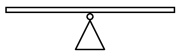
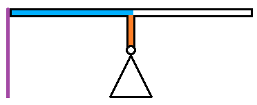
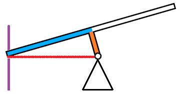
Now, consider if the seesaw beam was vertically offset upward from the fulcrum:
The axis of rotation is now away from the beam, instead of at the beam. The beam will rotate around an axis that is far away instead of at the beam.
Each half of the beam will be on opposite sides of the fulcrum only if the beam is horizontal, as shown above.
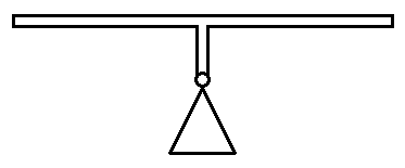
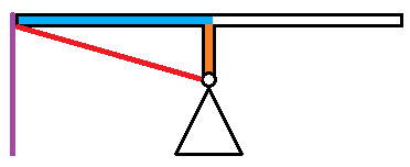
If the beam is not horizontal, more than half of the beam will be on one side of the fulcrum, and less than half on the other side:
Tilting the beam makes one side of this type of seesaw heavier than the other side of the seesaw, taking extra force to push or stop rotation around the fulcrum.
This extra force is called moment of inertia.
In the bridge failure, it took extra force to raise the anchor arm above its girder pier, in turn releasing that force downward on the girder pier.
Hypotenuse Spreading
Not only does having a displacement lever create additional collapse force, it also creates a hypotenuse that causes the anchor arm to dig into its girder pier, causing the pier to bend and break.
Superimposing this bridge design on the displacement lever seesaw diagram:
References
What is a Moment
MIT lecture notes
NTSB Hearing, 10 April 2024
Bridge design advocacy